
The Fire Alarm Systems with respect to wiring diagrams or loops are classified below.
- Basic Fire Alarm System used in Home
- Conventional Fire Alarm System
- Addressable Fire Alarm System
- Intelligent Fire Alarm System
- Wireless Fire Alarm System
1) Basic Fire Alarm System used in Home:
In household applications, mostly basic fire alarm system wiring is used with alarm detectors (smoke alarm detectors). The alarm detectors are installed at various locations of the home with the help of basic wiring.
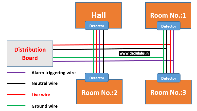
Fig. 1 shows the basic fire alarm system wiring used in the home. There are a total four-wire used i.e. alarm triggering wire, a neutral wire, live wire, and ground wire. The live wire is called hot wire or line and it has 110 Volt, 60 Hz or 230 Volt, 50 Hz value. The live wire, carrying current at high voltage and connected to the generator. After passing the electricity to the detectors and other appliances, the neutral wire (current-carrying conductor) is used to returns the electricity to the generator and closed the electrical circuit. In the case of a fault condition, the earth wire or ground wire is used as a safety protective wire for the user and electrical appliances.
As shown in fig. 1, The detectors are installed in a particular area of the home. All detectors are connected to each other and the distribution box.
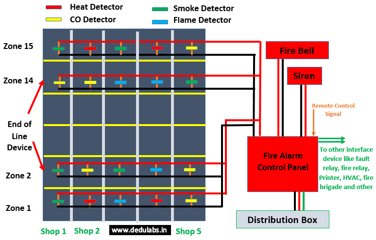
2) Conventional type Fire Alarm System:
In a conventional type fire alarm system, the inputs and outputs peripherals devices are interfaced with the fire alarm control panel using individual wire instead of shared wire. The smoke detector, flame detector, CO detector, heat detector, manual call points, and others are called inputs peripheral devices. The visual indicators (LCD display, LED display, seven-segment display, and others) and audible indicators (speaker, siren, horn, and others) are called outputs peripheral devices.
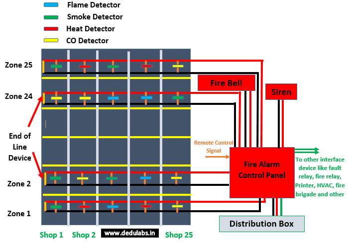
The wiring of a conventional fire alarm system for high rise commercial buildings (25 floors and each floor have 25 shops) is presented in fig. 2. Each floor of the building is considered a zone. As shown in fig. 2, the smoke detector, flame detector, CO detector, heat detector, visual indicators, and audible indicators are installed in various zone. As per user requirements, the manual call points are also used. The resistor with specific value is used as an End of Line (EoL) device and installed at the last device of the zone. With the help of the EoL device, the fire alarm control panel notifies the open condition, normal condition, and short condition. In case of fire, with the help of this type of arrangement, authorize a person or user easily identify the affected area.
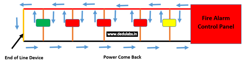
In conventional fire alarm systems “virtual eyeball” is used for continuous monitoring of a particular amount of power is coming back from the End of Line device installed at the end of the zone circuit arrangement. The Fire Alarm Control Panel (FACP) provides status of normal condition when the back power is within the set-point range as shown in the fig. 3.
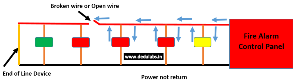
As shown in fig. 4, the power does not come back at the fire alarm control panel when the wire between FACP and EoL is broken. In case the detector is removed from its location, the circuit becomes open and the power does not come back at the fire alarm control panel. In this case, the FACP provides information about fault condition.

In case of fire, the detector detects the fire and the detector provides the closed path between the FACP and the EoL devices. The FACP provides information about fire detected conditions or fire alarm conditions. This condition is presented in fig. 5.
In this type of arrangement, user easily identified in which zone the fire is generated. The exact location of the fire is not identified. Therefore it is not possible to identify which device is triggered.
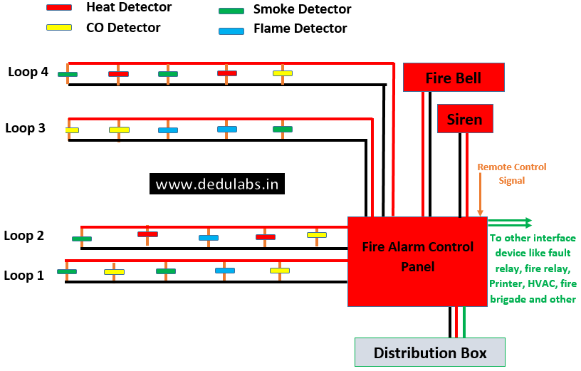
3) Addressable Fire Alarm System:
The wiring of addressable fire alarm system is shown in the fig. 6.
In an addressable fire alarm system, all detectors are connected in a loop with their own address. Due to a unique address, it is very easy to identify the zone and exact location of the triggered detector. As compared to the conventional fire alarm system, the addressable fire alarm system is costly.
In this type of arrangement, up to 99 devices are connected in a single loop and it covers up to 3.3 km detection range.
Each detector is designed with an isolation circuit. In case of a fault condition in a particular area, the affected area will be taking on the maintenance and remaining portion of the loop is work properly.
The addressable fire alarm system is integrated with Personal Computer-based Central Monitoring System (CMS) Software and mobile devices to indicate an unhealthy condition or the emergency condition.
4) Intelligent Fire Alarm System
The wiring of intelligent fire alarm system is shown in fig. 8.
The intelligent fire alarm system offers advantages of conventional and addressable fire alarm system. The intelligent fire alarm system provides the exact location of the fire.
The intelligent fire alarm system is used to prevent the faulty alarm condition with help of high accurate detectors, alarm notification devices, and others. This type of system is used to analyze the atmosphere condition around the working area and interface with the fire alarm control panel for performing various tasks when fire or faulty conditions occur. Intelligent Fire Alarm System also provides notification when any maintenance of the detectors, fire safety equipment, and others are required.
This type of arrangement is available with one loop, two loops, four loops, eight loops, and others. Each loop is capable of covering up to 3.3 km detection range with the connection of up to 99 detection devices. With the help of multiple loops, the detection range of fire alarm system is increase.
5) Wireless Fire Alarm System:
The blockdiagram of wireless fire alarm system is shown in fig. 8.
In this type arrangement, the interfacing between detectors, alarms, indicators, and fire alarm control panel is done through wireless communication. In case of fire or any other emergency condition, the detectors send the signal to the fire alarm control panel to enable the alarm.
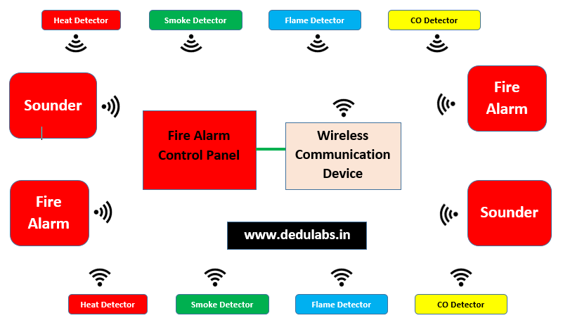
In the wireless fire alarm system, the wiring and labor cost is very less. Due to less wiring, the installation time of the fire alarm system becomes less. The detectors are used with transmitter circuits. The alarms and sounders are used with receiver circuits. The fire alarm control panel has a transmitter and receiver circuits. The investment cost of components is higher compare to other fire alarm systems.


 Users Today : 16
 Total Users : 41114
 Views Today : 50